

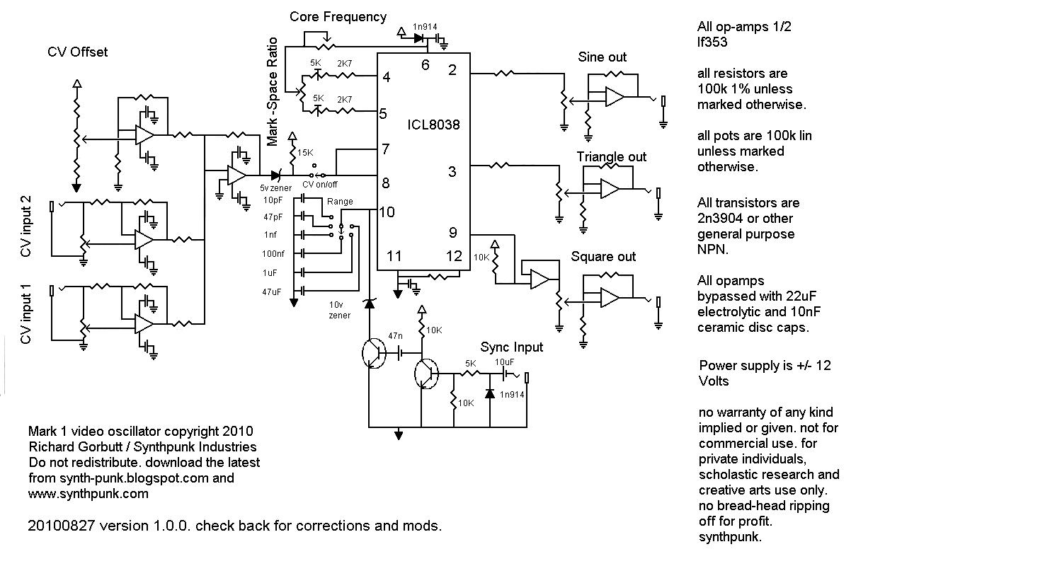
It runs from plus and minus 12 volts, and has a range of dc(ish) to over 100-200khz (as far as i can tell). it has a linearish cv response (within some ill defined and i suspect probably quite wierd limits that i havent looked into yet). it sounds quite good too at the audio end of things, and is a nice vcLFO for any type of modular. just adjust the timing cap values on the range switch to taste. big ones make it slower, smaller ones make it go faster.
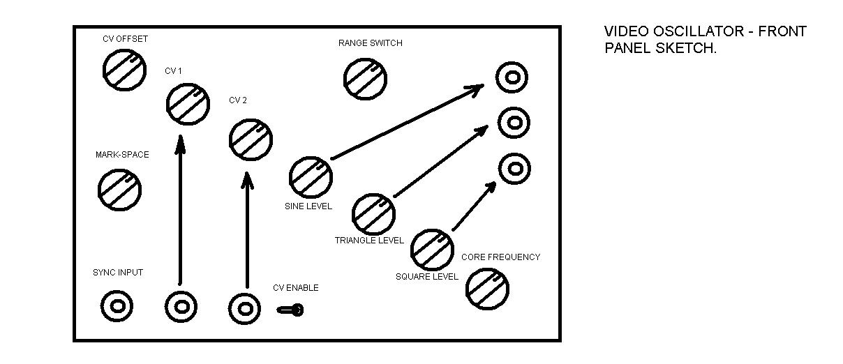
all parts are chosen to have as much similarity in values as is practically possible. its lots cheaper to buy 100 quality pots of the same value than to buy 100 cheap pots in various odd values and sizes. so for the most part, the pots are all 100k linear, the resistors are mostly 100k 1% metal film, and if you want it to work well, all wiring is with RG178 shielded coax except the power supply which is thickish hookup wire. it has attenuverting inputs, and also level controls on the outputs. as in the sandin (which the sync circuit is blatantly borrowed from!) you can disconnect the CV inputs from the oscillator core to improve stability for oscillators that dont need modulating. signal levels are pretty high, and it seems to tolerate ten volt bipolar CV input .levels too. bonus. the CV trim control sets the offset to the modulation voltages, which means you can get some fairly precise control over the modulation points. its not easy to explain, and confused the crap out of me the first time i used it, but it seems to work quite well for trimming out (or adding in) distortions in the modulated waveforms..
if you want to build it, email me and ill let you have any further updates that arent on this site yet. i recommend prototyping it on a breadboard first.
here is the PCB layout i used. i havent done a component overlay yet, ill get on it. there are probably errors. YMMV.