for music synthesizers.
The previous version can be found here.
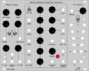
The name of this module is a play on its function. Put simply, it generates a series of semi-random or themed stepped control voltages, or if you prefer, white and pink control voltages. The pink function is probably better known as 1/f, and thus the name of “1l/lfinite melody”.
Assuming a 1 v/oct VCO is being driven by the module, in the 1/f mode, the size of a pitch step is inversely related to the frequency at which it will occur. In other words, the smallest steps are most common, steps twice their size occur half as often, and so on.
As well as the 1/f mode, it has a pure random mode, where no weighting is put on the selection of notes. A large step is as likely as a small one.
As well as having these two modes of operation, there are 4 CV outputs available. With the exception of the fourth, each successive output is a shifted version of the previous. In random mode, this is very much the same effect as produced by an Analog Shift Register (ASR), but in 1/f mode, it takes on a whole new feel, as each of the six shift registers involved shifts at a different rate, according to the 1/f weighting. As such, the second and third outputs are related to the first, but not identical to it. The fourth output is subject to the same shifting weighting according to the mode of operation, but instead of driving a D/A converter, it drives a bank of knobs, allowing harmonic relationships to be set up.
And if that wasn’t enough, the randomness used by this module is obtained externally, from a regular white noise generator, or other varying voltage source, allowing more structured themes to be created. The random values are loaded in series at a rate determined by an external fast clock. This can simply be a spare output of a VCO (even one in use playing melodies etc.) or it can be deliberately controlled, or slowed right down to gain even more effects. The sensitivity of the random input can also be controlled via CV, again giving more possibilities.
See Diatonic Converter for an alternate output for this module.
A little on how it works:


First, a very simple theory lesson – 1/f implies a weighted ratio between a level and its corresponding rate. A change in level of 1 will occur at the clock rate. A change in level of 2 will occur at half the clock rate, a change in level of 4 will occur at a quarter of the clock rate, etc., thus giving rise to the 1/f ratio. This means the larger the step in output level, the less frequently it will occur. On the other hand, random implies exactly that – there is no determination of how great a step will occur – any step size is as likely as any other.
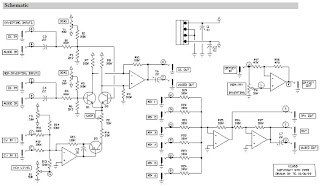
As is shown in the schematic, the Infinite Melody consists of several distinct sections.
The first section is the clock and random or 1/f selector. The clock and reset signals are processed by the LM358. When the 1f/Ra input is LOW (below about 2V), the reset line of the 4024 will be held LOW, allowing it to count, and clock signal connected to the second input of each EXOR gate via the 10k resistor will be blocked by the forward biased diode. The output of the counter is then fed via the EXOR gates (inverted in the process) to the clock inputs of each of the 4015 shift registers. Each successive shift register receives it’s clock at half the rate of the one above it.
When the 1f/Ra input is HIGH (above about 2V), the reset line of the 4024 will be held HIGH, forcing all of the outputs of the 4024 to LOW. The clock signal connected to the second input of each EXOR gate via the 10k resistor will pass as the associated diode is now reverse-biased, and no longer blocking the signal. The clock signal is now fed via the EXOR gates (inverted in the process) to the clock inputs of each of the 4015 shift registers. All shift registers are now being clocked at the same rate.
The second section of the schematic is the random number processor. Each shift register in the chain requires a random level to be present at its data input when it receives its clock signal. Traditionally this would be achieved by having a series of six independent random number generators. Instead it was decided to clock random data in serially at a rate significantly higher than needed. This section is essentially identical to the Gated Comparator, so I suggest you investigate that article for more information on how it works.
 The block diagram of the Infinite Melody.
Construction

| The component overlay for the VER2.0 PCB. Click here for an enlarged, printable version. Print at 300dpi. |
Before you start assembly, check the board for etching faults. Look for any shorts between tracks, or open circuits due to over etching. Take this opportunity to sand the edges of the board if needed, removing any splinters or rough edges.
When you are happy with the printed circuit board, construction can proceed as normal, starting with the resistors first, followed by the IC sockets if used, then moving onto the taller components.
Take particular care with the orientation of the polarized components, such as electrolytics, diodes, transistors and ICs.
When inserting the ICs in their sockets, take care not to accidentally bend any of the pins under the chip. Also, make sure the notch on the chip is aligned with the notch marked on the PCB overlay.
The master level pot for the mix-out is optional. It can be omitted if the resistor marked 27k* is installed. If using the pot, do not install the 27k resistor.
Euro rack users can cut the PCB along the row of holes, and double the board back on itself. You will need to install links between the two parts of the PCB. Pads are provided for this. There are two mounting holes that match on each board, allowing them to be secured to each other.
Pad identification
| 0V | 0V/GND connection for 3.5 or 6.5mm jacks and CCW end all mix bit pots. |
| CLK | Clock input to advance the melody. “ADVANCE” on Best of GCS panels. |
| -V | -VE access point if required. |
| MSW | Common contact of MODE switch. |
| MB0 | Mix bit. Goes to CW end of corresponding mixer pot. (1 on Best of CGS Panel) |
| MB1 | Mix bit. Goes to CW end of corresponding mixer pot. (2 on Best of CGS Panel) |
| MB2 | Mix bit. Goes to CW end of corresponding mixer pot. (3 on Best of CGS Panel) |
| MB3 | Mix bit. Goes to CW end of corresponding mixer pot. (4 on Best of CGS Panel) |
| MB4 | Mix bit. Goes to CW end of corresponding mixer pot. (5 on Best of CGS Panel) |
| MB5 | Mix bit. Goes to CW end of corresponding mixer pot. (6 on Best of CGS Panel) |
| BD4 | To common connection of optional bit 4 disable switch. |
| BD5 | To common connection of optional bit 5 disable switch. |
| LA | Sense LED Anode |
| LC | Sense LED Cathode |
| P1 | Gain pot connects between the two pads marked P1. Wiper is wired to CW end of pot. POT HAS NO 0V CONNECTION. |
| O1 | Output for sequence 1 |
| P2 | Gain pot connects between the two pads marked P2. Wiper is wired to CW end of pot. POT HAS NO 0V CONNECTION. |
| O2 | Output for sequence 1 |
| P3 | Gain pot connects between the two pads marked P3. Wiper is wired to CW end of pot. POT HAS NO 0V CONNECTION. |
| O3 | Output for sequence 1 |
| PM | Optional master gain pot connects between the two pads marked PM. Wiper is wired to CW end of pot. POT HAS NO 0V CONNECTION. |
| OM | Output for mixed sequence |
| MIX IN | Each goes to the wiper on oneof the mix bit pots. There are two extra inputs that can be wired to external input jacks, or an offset pot. |
| SV | Sense control voltage input. If using a panel that has a level pot for this input, wire the jack to the CW end of a 100k linear pot. The CCW end goes to 0V and the wiper goes to the SV pad on the PCB. |
| ST | Initial Sense voltage setting pot CW end |
| SC | Initial Sense voltage setting pot wiper |
| SB | Initial Sense voltage setting pot CCW end |
| RI | Input for random analog or digital pulse train |
| +V | +VE access point. To one side of mode switch. |
| RC | Fast clock for random loading, for example from any VCO in your system, even if it is being used for other purposes at the time. If you are hardwiring to CGS31 digital noise board, this can go to the output of the CGS31’s onboard VCO. |


| An example of hard wiring the Infinite Melody board. If building the unit into a Best of CGS panel, the Channel Gain pots are replaced with fixed resistors soldered directly to the PCB. 100k will give unity gain. Smaller value resistors, resulting in smaller steps may be of more use to some people. On this example the 27k marked “27k*” is installed, and the master gain pot (GM pads) is not used. |
|
|||||||||||||||||||||||||||||||||||||||||||||||||||||||||||||||||
Notes:
- This module will work on +/-12 volts.
- Make sure you use a standard 4000 series CMOS, not 74XXX4000 series, e.g. CD4015, MC14015, HEF4015.
Markings such as HC4015, HCT4015 imply 74HC4015 and 74HCT4015 and are unsuitable. - If you don’t care about power-rail noise, just use a link instead of the ferrite beads.
- PCB info: 6″ x 3″ with 3mm mounting holes 0.15″ in from the edges.
- Please email me if you find any errors.
Parts list
This is a guide only. Parts needed will vary with individual constructor’s needs.
If anyone is interested in buying these boards, please check the PCBs for Sale page to see if I have any in stock.
Can’t find the parts? See the parts FAQ to see if I’ve already answered the question. Also see the CGS Synth discussion group.