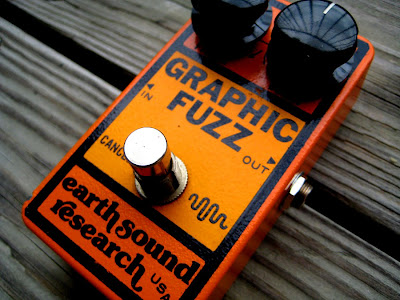


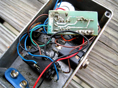
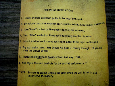

Earth Sound Research Graphic Fuzz (1976)
Posted in Uncategorized
Comments Off on Earth Sound Research Graphic Fuzz (1976)
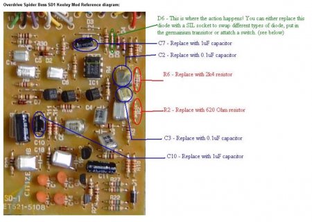
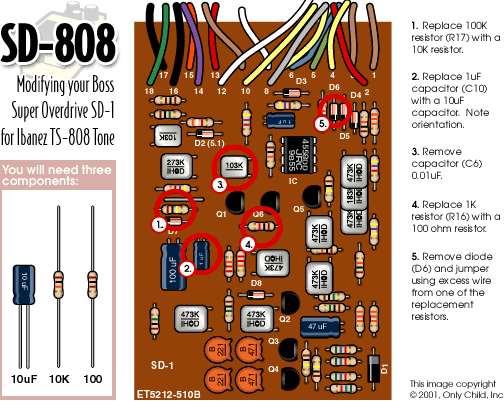
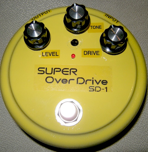
Boss SD1 Super Overdrive Modification

Free Pedal Day!
Finally got it…
was actually newer Boss SD1 Super Overdrive…
Posted in Uncategorized
Comments Off on Boss SD1 Super Overdrive Modification
Germanium transistors : Black Glass models
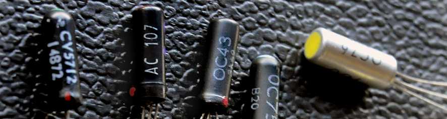
They were thus nicknamed in allusion of their very particular black glass case. Glass technology had been selected because at that time plastics were still unable to ensure a perfect seal between case and terminals. They have been the first transistors widely available, and the aged electronic techs have fond memories of them. It must be said they are found in the earliest fuzz, the first solid state professional audio systems and computers.
This is an opportunity to discuss the properties of the main types and identify their ability to be used in circuits devolved to guitars .
NB: I will only talk about transistors that I actually had in hand.
What were the Black Glass worth ?
They were fragile, a bit noisy — especialy the very first. Their leakage current, the generic defect of germanium transistors, is a bit higher than in later models. Forty years later I found them generally quite musical: Almost all of them combine a sonic color and a texture that makes them exploitable in preamps or boosters, overdrives and especially in fuzzboxes.
Some have been used in historical stompboxes by Arbiter, Sola Sound, Vox, Marshall.
Some were high-quality designed for the first computers. Others have been rediscovered by cloners, in replacement of the classics.
All glass models
OC70
The first Black Glass. It is fragile, noisy and a bit too low gain.
One of the few that are really obsolete.
OC71 or OC72 are preferable.
OC71, OC72
Rustic general purpose models. Proper gain for a fuzz. Average leakage, fairly mild tone.
OC75
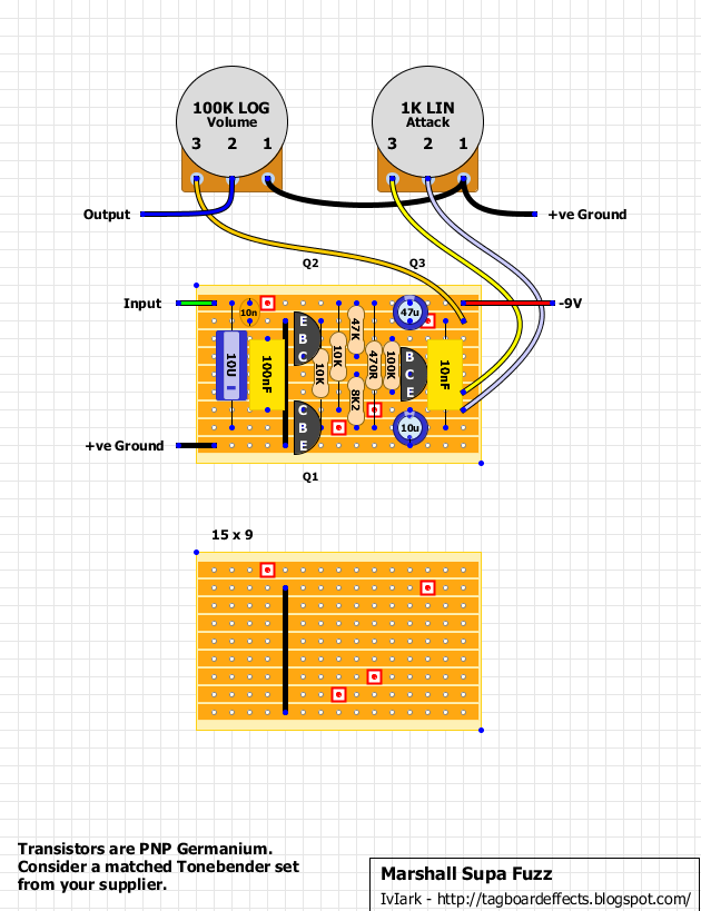
Common at the time. Used in some historical three transistors Fuzzboxes like The Marshall Supa Fuzz and some 2 transistors Tone Benders. Highly sought and expensive.
Intense midrange grained texture make it perfect for Fuzz, but not so easy to implement…
Often leaky, not easy to bias, but can sound great.
AC107
One of the latest Black Glass, using the new ACxxx code. Rare and pricey.
They were used in professional audio preamps. Remarkable distinct and smooth tone.
Some later models in TO1 metallic case seem to be low class markdowns…
OC203, OC613 and similar (code >200)
Transistors of these series are not germanium, but early silicium models.
Poor quality indeed. One may and should forget them…
Encapsulated models
Around 1964-65, the glass enclosures were encapsulated in aluminum, more rarely in plastic, to make them stronger.
OC72, OC74, OC76
Higher gain development of the early OC71-72. Work rather well.
OC74 was rediscovered by the cloners of the 90s, and is good in fuzz boxes.
OC76 stands out by its sound clarity. For those who like a sharp distortion.
It may have been used in some 2 transistors Vox Tone Benders.
OC81, OC83, OC84
Particular models made to drive output transistors. Good for fuzz.
OC81D is as much sought as OC75, because it also equipped historic Tone Benders.
OC139 (aluminium cover), OC140 (all glass)
Professionals models, the first NPN developed for computers. Rather rare and pricey.
Give very reliable Fuzz, with homogeneous and clear sound, and accurate overdrive.
They are a good solution in putting germanium transistors into a standard negative grounded circuit without transforming it.
High frequency transistors
OC43
First Black Glass developed for computers. Rare and pricey.
Very reliable. Low leakage and easy to bias. Homogeneous tone without special color.
Good for boosters or preamps.
OC44
Among the first germanium, dedicated to radio frequencies. Slightly leaky.
OC44 is suitable for boosters and preamps. It equipped the Rangemaster by Arbiter …
It can be advantageously replaced by AF124.
OC45
Less high frequencies than previous ones, but very little leakage, therefore reliable and easy to bias, but lower gain. Same qualities in treble boosters and other preamps.
It can be advantageously replaced by AF124.
AF115, AF116
These are not encapsulated black glass, but already Philips-Mullard TO1 boxed.
One may cite them here as early germanium high frequency transistors, designed for Frequency Modulation receivers. They have a fourth connection, enabling the housing of the transistor to be connected to ground.
These models are very fragile, sensible to static electricity, and therefore to avoid.
AF124, AF125
These are later models in metallic TO1 long box. They are much more reliable and less noisy than AF115-116 and better performing than OC44-45.
They can be used to build very nervous preamps or boosters, especially modern versions of the Rangemaster or Screaming Bird.
Guitar Poppa
Second edition, july 2017
Posted in Uncategorized
Comments Off on Germanium transistors : Black Glass models
Dallas Rangemaster Treble Booster Analysis
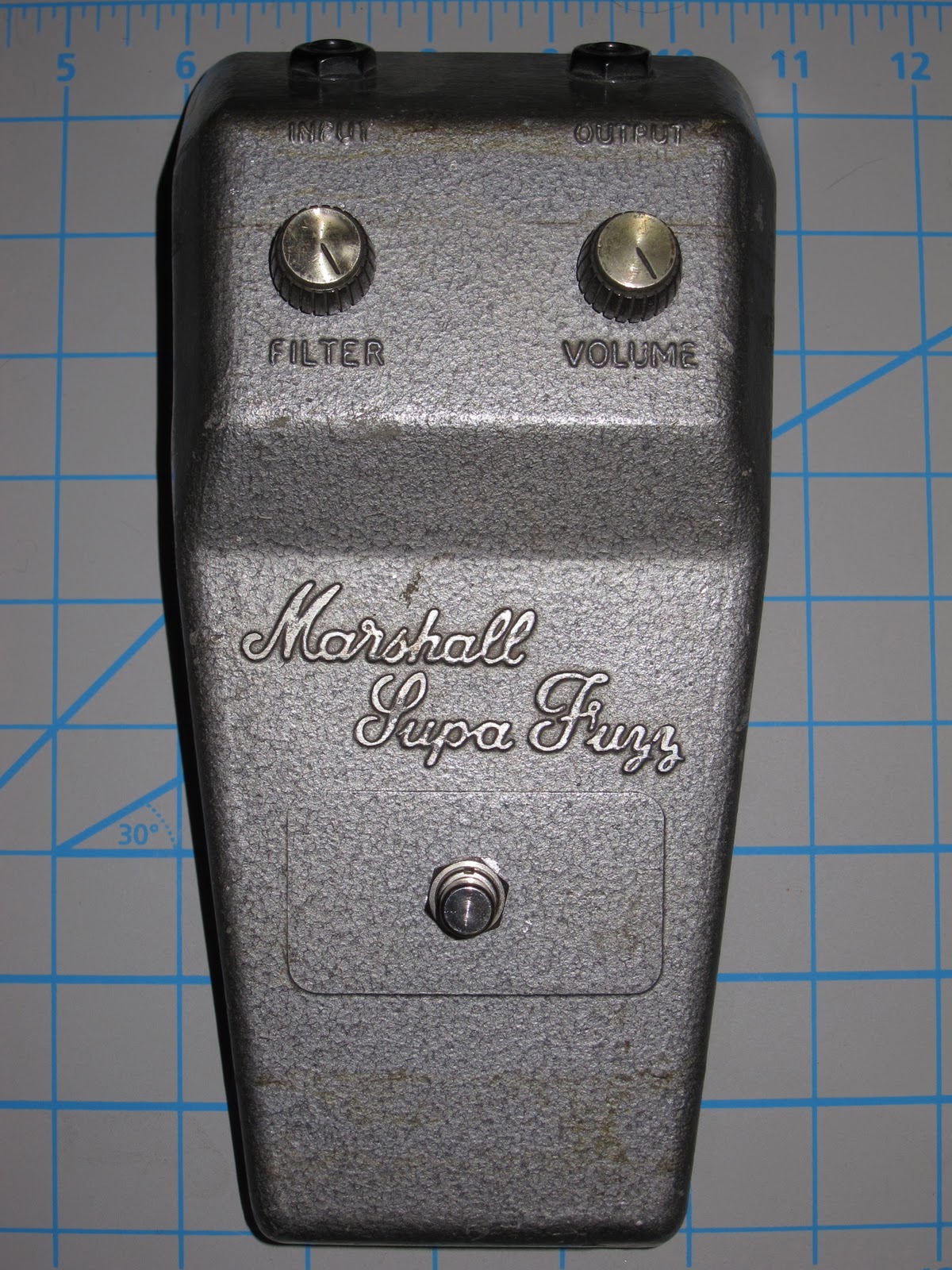
The Dallas Rangemaster Treble Booster is a booster guitar pedal that especially emphasizes the upper mid and treble frequencies (coloring the signal). It was designed in London (UK) by Dallas Musical Ltd in 1965. At that time, the British tube amplifiers such as the Vox AC30 or Marshall JTM45, tended to produce a slightly dark, muddy tones when overdriven, this box fixed that issue. The effect became popular because of its sweet coloration, slightly bending the signal and giving a soft compression when maxed out.

The grey metal box was designed to sit on top of the amp and not on the floor as most of the pedals do nowadays, it features a simple ON/OFF sliding switch and a potentiometer to adjust the volume. The apparent simplicity of the circuit and the limited supply of this discontinued effect make it a perfect target for builder and guitar pedal enthusiasts.
1. The Dallas Rangemaster Original Parts:
The Dallas Rangemaster was designed with the available parts at that time (the 1960’s), carbon comp resistors, Mullard germanium transistor, no PCB (all the components are mounted over a piece of a terminal strip), an exotic English potentiometer, etc:

- Carbon Comp Resistors: Carbon comp is an old technology, noisier than modern metal film 1% resistors. These vintage resistors could bring more organic sound (but also are blamed to bring the noise). For other vintage effects like the Fuzz Face that (noisy by definition), carbon comp resistors are a great choice (adding a bit more noise to a high gain fuzz wont hurt anyone). On the other hand, for a booster (like the Rangemaster) maybe carbon comp technology is not a good idea (you want to keep all as clean as possible), so modern film resistors are a better choice.
![]()
- The potentiometer: The original Dallas Rangemaster uses a UK Welwyn 10k ohm (sometimes 20k) unit with two mounting screws. The potentiometer body was made of bakelite and isolated from the chassis, but this feature does not add any benefit for the pedal.

- The original Germanium transistor was the Mullard OC44, long time ago discontinued. They are claimed to sound good with a soft clipping knee but also noisy, microphonic, temperature dependent and gain variable.

- Capacitors: There is not much magic involved on the caps, they are just common available technologies: 47uF is aluminum electrolytic, de 5nF and 10nF are films.
![]()
2. Dallas Rangemaster Treble Booster Schematic.
The circuit is beautifully simple, a single stage Common Emitter PNP amplifier:
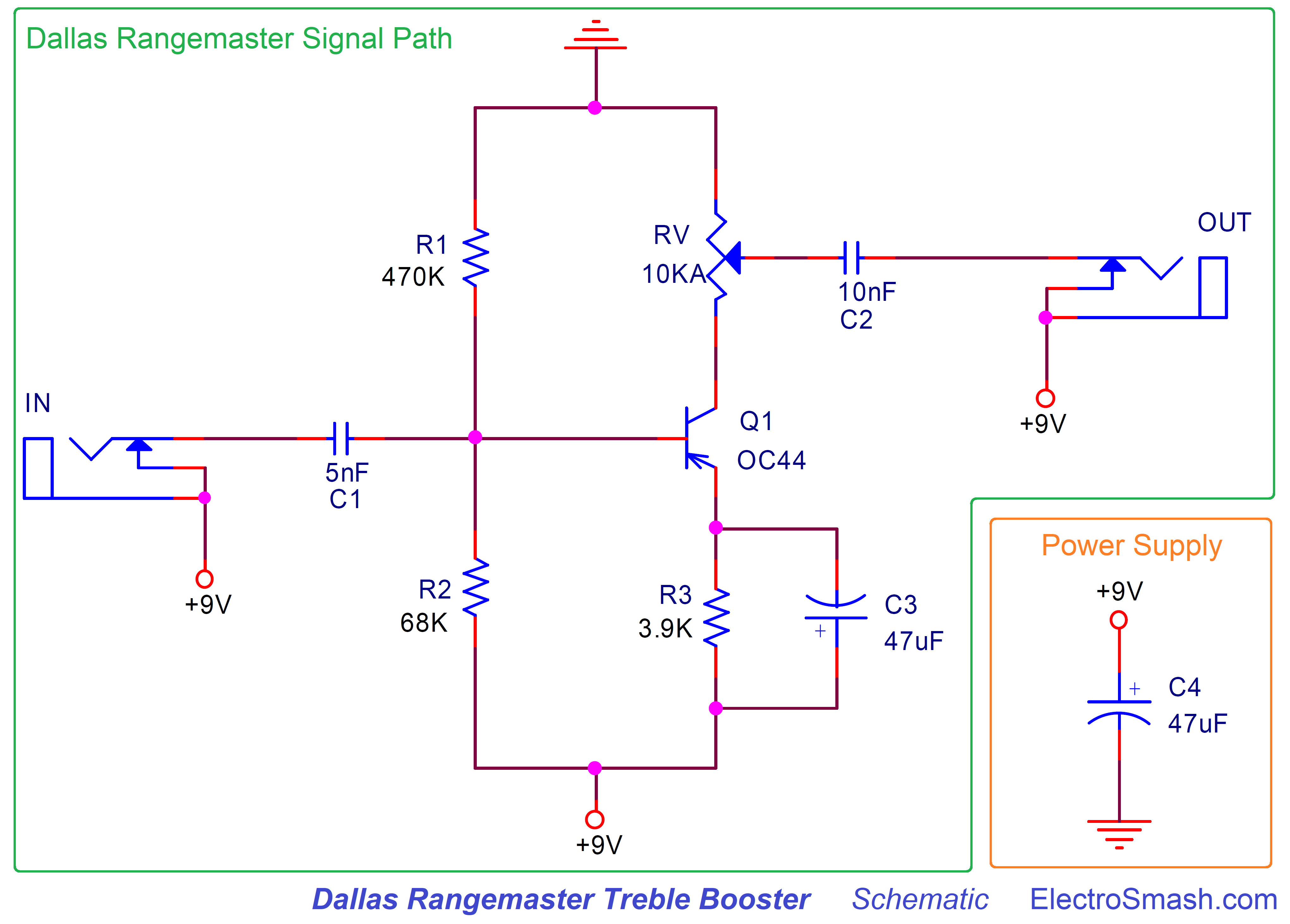
- C1: Is the series 5nF input cap, it will remove any DC level from the input signal and also create a high-pass filter together with R1, R2 and the input impedance of the Q1 transistor. This cap is crucial for the pedal equalization. You can read about this filter in the Frequency Response section and also in the Mods part.
- The resistors R1 (470KΩ) and R2 (68KΩ) create a Voltage Divider across the supply. They provide the required bias voltage to the base of the transistor and define the operating point of the pedal. Biasing the pedal in this way (with a resistor divider in Q1’s base) reduces the effect of β (gain) variations, which is pretty common in Germanium transistors.
- RV: Is an audio (logarithmic) 10K potentiometer. It will control the amount of volume of gain applied to the input signal, check the Voltage Gain section for more info.
- R3: is a 3.9KΩ emitter resistor for the Common Emitter amplifier, it will provide negative feedback to the transistor, keeping the bias point stable.
- C3: 47uF electrolytic cap, makes the guitar signal to bypass the R3 resistor. This makes the signal to get higher gain despite the bias point established by R3.
- C2: it is the 10nF output series capacitor. Its task is to clean any DC for the output signal.
- C4: The power supply is simply formed by a single 47uF, there is no protection against reverse polarity connections but makes sense because the original effect was designed to work only on battery. If you want more info about power supply improvements/mods, check the modifications section.
2.1 Dallas Rangemaster Input Impedance.
The input impedance could be calculated as:
Zin = (R1//R2) // (Zin transistor)
Zin = (R1//R2) // (rπ) = 470KΩ // 68KΩ// 12.5KΩ = 10KΩ to 12KΩ approx.
Where:
rπ = [(β+1)xVt]/Ieq = β/gm = 100/0.008 = 12.5KΩ
β = 100, we are using this value by default in the whole article, you can do the numbers using any other value.
gm = Ie/Vt = 0.2mA/25mV = 0.008
Ie= 0.2mA you can check how this is calculated in the biasing section.
The “//” symbol means “resistors in parallel”.

As a rule of thumb, a high input impedance (around 1MΩ) is always desired; it reduces tone sucking, pickups loading and possible interactions/interference between pedals.
12KΩ is a poor input impedance value (Zin), but part of the Rangemaster sound owes its fame due to the way its low Zin interacts with passive pickups. This loading will smooth the highs and helps the guitar volume control the clean it up. So, the input impedance is an important factor on the pedal’s tone, if the effect is not driven by a guitar but by a high input impedance buffer, the Rangemaster may sound bright and thin. This is why many people like to place this effect the first in the pedalboard (or keeping it in an isolated loop)
2.2 Dallas Rangemaster Output Impedance.
The output impedance in a Common Emitter amplifier is Rv (the transistor’s Rc).
Zin = RV = 0 to 10KΩ
Ideally, a guitar pedal design aims for low output impedance, it makes the circuit to interact nicely with the rest of the pedals on the board. 10K is not bad; most of the designs keep the output impedance below 1K but 10K is still good.
The C3 cap that bypasses the R3 resistor makes the voltage gain formula:
Gv = gm x Rc = 0.008 x 10K = 80 = 38dB.
note:
- gm = 0.008 it was calculated in the Input Impedance section.
- 38dB is a high voltage gain for a booster pedal, other similar pedals like the MXR MicroAmp have a lower voltage gain of 26dB. This is not necessarily a good or a bad thing, but the Rangemaster will for sure be able to drive signals harder.
Note: The DC Voltage across the Volume control: The electronic design of this pedal makes that the RV potentiometer keeps a DC voltage across its terminals. This means that the sound will scratch and whenever the volume is touched (even if you use the original plastic- non-conductive original discontinued Wilk potentiometers)
2.4 Dallas Rangemaster Signal.
The maximum swing operating point in the Rangemaster happens when Vb=7V approx. and Vc=4V approx. But as you will see in the Bias Section, the considered best sounding biasing happens with Vb=8V approx. and Vc=2V approx. The transistor amplifier is not at the center of the linear region, and it will result in an asymmetric soft clipping:

When the Vol control is maxed out, the signal will be boosted and also driven into soft clipping, this will color the signal and make the sound quite particular. Germanium parts are famous for their soft clipping and biased off the middle of its swing area, the signal will be compressed in one of their semi cycles, making the sound asymmetrically warmer and rounder.
3. Dallas Rangemaster Treble Booster Frequency Response.
The frequency response is dominated by the high-pass filter created by the C1 and the input impedance of the pedal. But there are 2 more caps (C2 and C3) that also create high-pass filters:
- C1: creates a high-pass filter with a fc=1/2πC1xZin = 1/(2 x π x 5nF x 12KΩ) = 2.6KHz
- C2: creates a high-pass filter with a fc=1/2πC1xRload = 1/(2 x π x 10nF x 1MΩ) = 15.9Hz (not in the audio band)
- C3: creates a high-pass filter with a fc=1/2πC3xR3 = 1/(2 x π x 47uF x 3.9KΩ) = 0.8Hz (not in the audio band)
The most important filter for the audio response is C1, attenuating the harmonics below 2.6KHz and giving full gain to the treble.

The magic of this equalization is that frequencies over 2.6KHz will have full gain and a soft clipping when the strings are strummed hard. Giving some warm tone to the high frequencies.
4. Biasing the Dallas Rangemaster Treble Booster:
Germanium transistors have an Hfe (also called β and Gain) value that changes from part to part. As a result of that the bias point of the pedal will change from one unit to another, to fix that and try to make the best sound out of the pedal we have two options:
- Find the germanium transistor with the perfect HFE gain 90: Any value between 75 and 100 would be great. The problem is that germanium transistors went out of fashion 30 years ago, there are no lines of production and finding NOS batches with a decent gain is almost impossible. In the ’60s this was a viable option, nowadays not so much.
- Bias the circuit properly: When Dallas designed the Rangemaster, they probably had access to good transistors with controlled gain, so they just set a pair of fixed resistors (R1 and R2). Now that the transistors are not so numerous, we can just adjust this 2 resistors and make the pedal sound its best.
The sound of the Rangemaster is heavily dependant on the bias point. Usually, transistors are biased to the middle of their swing area so they can produce the biggest non-distorted output signal (maximum headroom). This is not the case of the Rangemaster, where the bias is a bit off the center creating an asymmetric gain.
The Perfect Bias point:
It is commonly agreed that the ideal bias point for the Dallas Rangemaster Treble Booster is to have Q1 collector voltage at -7.0V (any value between -6.9 and -7.1 would be great), if you refer the voltage to ground and not to +9V (like the image below) the perfect Vc=+2V ( any value between 1.9 and 2.1).
The easiest way to achieve the best sounding bias is to substitute the 69KΩ R2 by a 100KΩ or 200KΩ trimmer resistor (a Bourns multiturn resistor is expensive but the best part for this task):
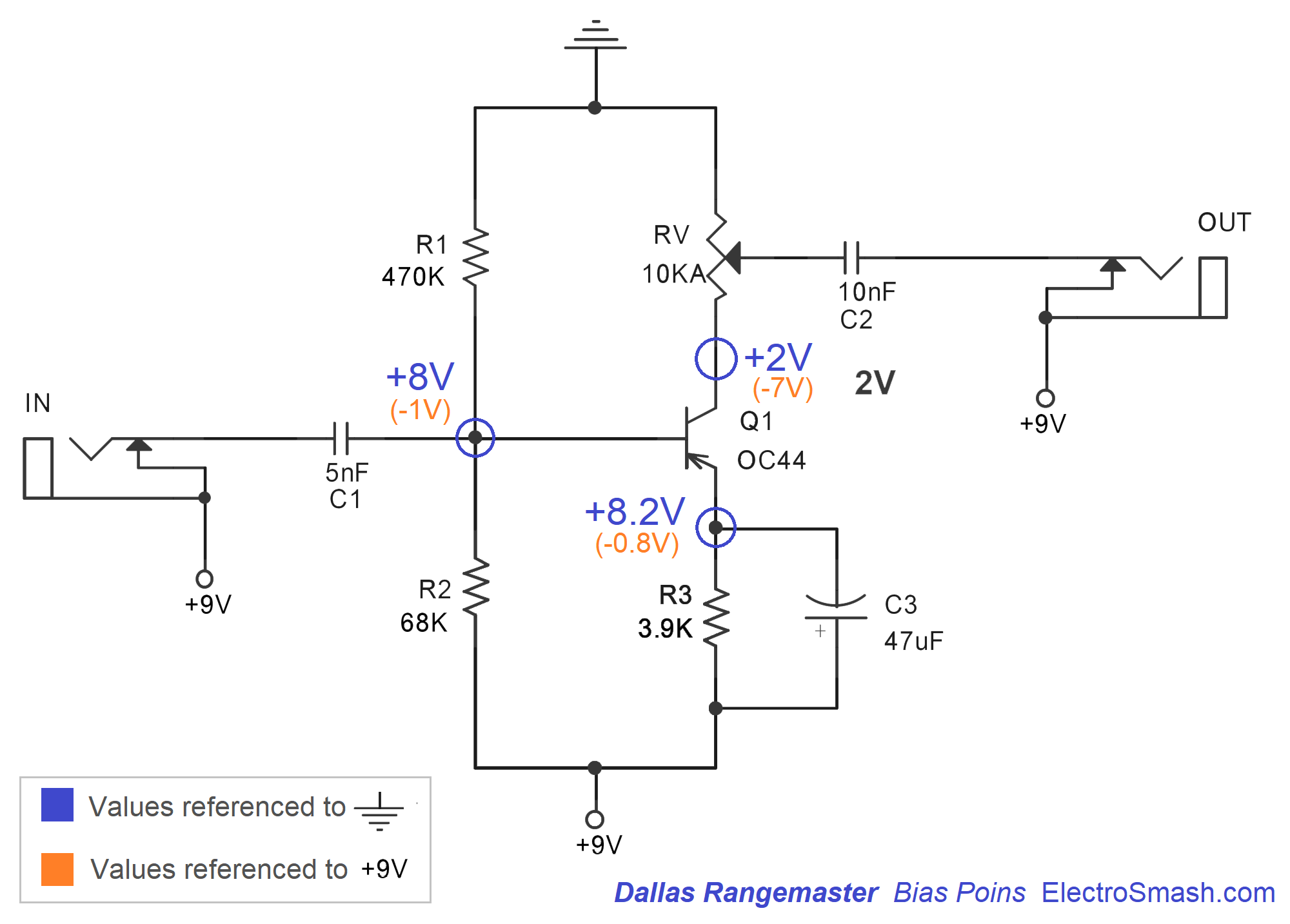
Calculating the Base voltage:
Vb = Vcc x R1/(R1+R2)/= 9 x (470KΩ/(470KΩ + 68KΩ)) = 7.8V (8V approx.)
The Base voltage (defined by R1 and R2) will determine the Base current:
Vb = Vbe + (β+1) x Ib x R3
ib = (Vb – Vbe) / (R3 x (β+1))
ib = (7.8 – 0.3) / (3.9KΩ * (100+1))
ib = 0.0195mA
note:
- Vbe=0.3V for most of Germanium transistors.
- We are using a default value of transistor Hfe = β = 100
The collector current and Collector Voltage will be:
Ic = β x ib = 100 x 0.0190= 1.9mA (2mA approx)
Vc= -Ib x Rv = -0.2mA x 10KΩ = -2V.
It is important to understand, that following the equation, if the β value changes, the bias point will change too. This is why using a trimmer resistor instead of R2 will compensate for this β variation.
4.1 Effects of the Bias Point over the Output Signal.
The bias point has a direct effect over the output waveform shape and the sound of the Rangemaster. In the image below you can see the output signal with different Vb values when the Volume knob is maxed out:
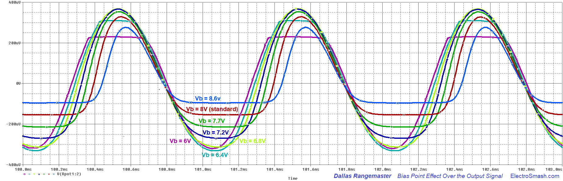
You can see how the default configuration (Vbase=8V) is not the cleanest option. Setting a Vb=6.8V (7V approx.), like the light green trace will give us more headroom and clean sound. But part of the character and mojo of this pedal remains on its biasing.
note: For all these graphs we have used a Q1 transistor with gain = 100.
5. Dallas Rangemaster Treble Booster Mods.
The simplicity of the circuit makes builders experiment adding some extra features so players can have some more knobs and switches to play with.
5.1 Positive / Negative Ground Circuits.
There are 4 ways to ground the Rangemaster circuit:

- PNP Positive Ground: it is the original circuit. It sounds fantastic but the problem with it is that if you want to use an external DC adapter (and not only batteries) it will create a short circuit (see how the input and output jacks are referenced to +9V and not ground). The original box never faced this issue because it only works on batteries. So please do not use a daisy chain power adaptor with a positive ground guitar pedal.
- PNP Negative Ground: it is a modern mod that adapts the pedal to be used with a standard daisy chain power supply. The input and output caps remove any DC so the input/output jacks can be re-grounded to the real GND. The problem with this approach is that the circuit would be very prone to oscillations/hissing/motorboat noise. The long return currents from the input and output jacks make the pedal unstable. Most of the times, it would work, especially because the Rangemaster does not have a massive gain ( like other popular PNP Negative ground circuits like the Fuzz Face that are very problematic), however, I would not recommend this circuit. If you want to use a real negative ground circuit, use the last option (MAX1044 mod).
- NPN Negative Ground: Using an NPN transistor, the pedal can be grounded in a standard manner, removing any problems with power supplies and oscillation. Any low gain NPN transistor would work here: 2N5088, 2N3904, 2N4401, BC108, BC109, BC109C, BC183, BC183L, BC209C (all of them are Silicon). The problem with this circuit is that there are not so many NPN germanium transistors out there.
- PNP Real Negative Ground: We can use a MAX1044 (or the equivalents: ICL7660, TC1044) to create a “real” -9V. You can use this -9V in the circuit making it compatible with a daisy chained power supply and without oscillation. Note that you have to be careful with the MAX1044 layout to reduce any noise from the charge pump. This mod is also used and described on the Radian Rangemaster Project by Aion Electronics.

The Dallas Rangemaster Input Cap modification is the most popular one. By simply changing the C1 input cap we can transform the frequency response making it more limited or wide. It is easy to implement, just using an ON-OFF-ON SW1 switch. There are two typical sets of cap values (5/10/15nF and 5/47/100nF) that you can use for this mod:
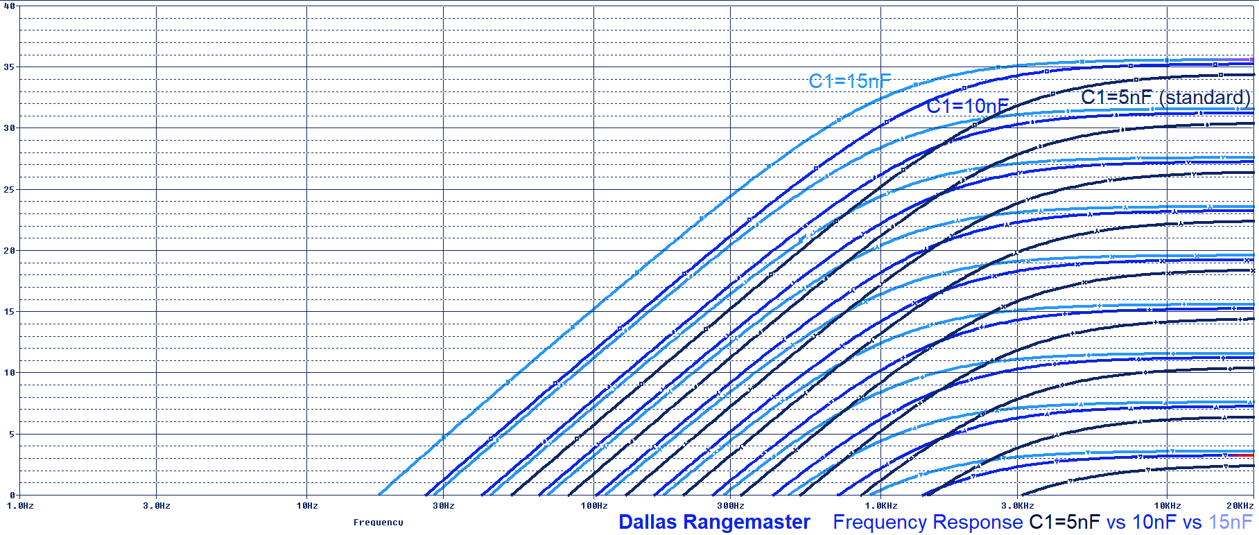
- If you want to keep the original tone of the Rangemaster and make subtle adjustments over it, the typical values are 5nF (standard value), 10nF and 15nF. Check the graph below to see how the frequency response is modified:
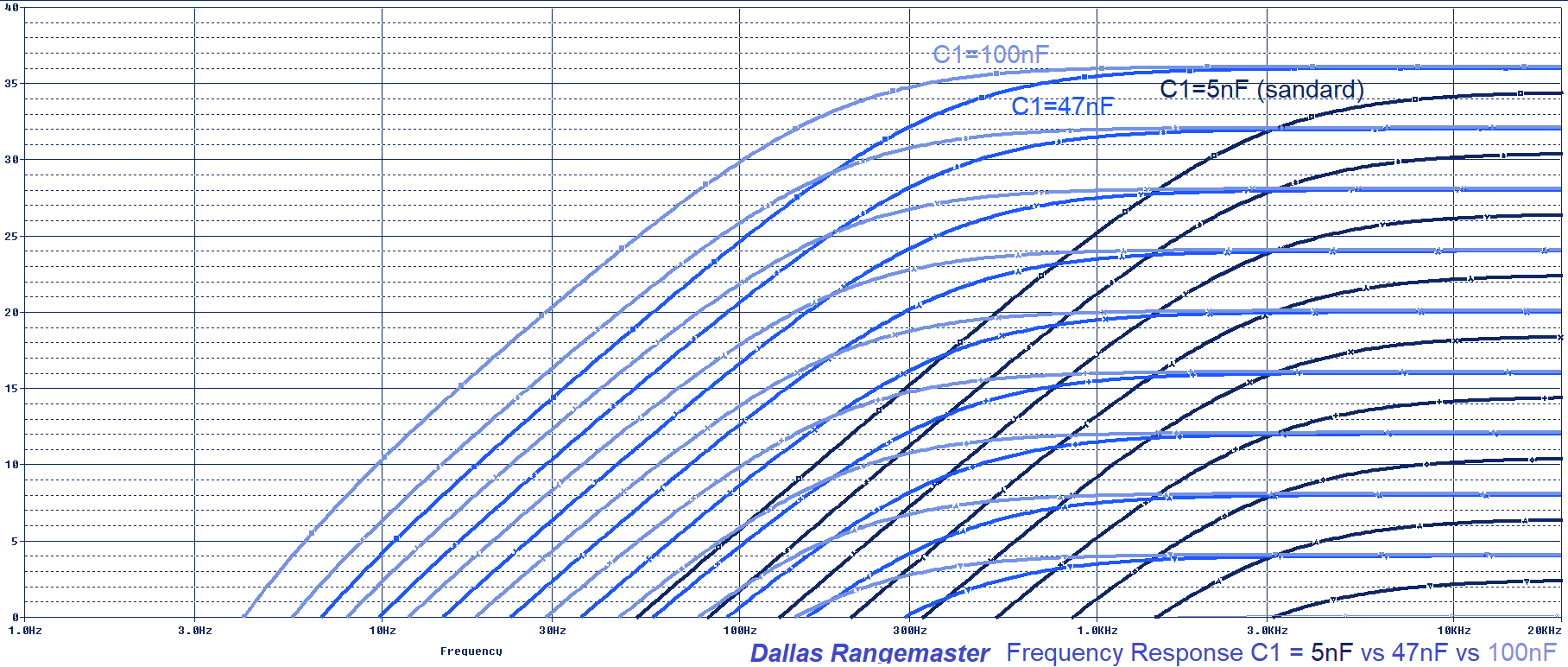
- If you want to be more aggressive, some players use the 5nF (standard value), 47nF and 100nF. This values are far from the original sound but may make the pedal more versatile, making the booster more wide frequency and not just for the treble. Check the graph below to see how the frequency response is modified:
5.3 Dallas Rangemaster Output Cap Mod.
This modification is not as popular as the Input Cap Mod and for a reason. Although it has to be admitted that 10nF is a low value for an output cap (many pedals use caps in the 100nF to 47uF range for this). Changing the C3 value will modify the filter created by this cap and the “load” or next pedal/amplifier in the chain. Users have different setups or “loads” so the result is variable.
In the same way, as in the Input Cap Mod, this feature could be implemented by using an ON-OFF-ON switch to change between 1nF, 10nF (standard value), 1uF. But if you have a good load (around 100KΩ to 1MΩ) the cut-off filter frequency (fc=1/2piRC) will not affect the audio band.
5.4 Input Pull-Down Resistor: The original Rangemaster was designed to be used between the guitar and the amp, with no other effects around. If you plan to use it together with other effects is recommended to use a pull-down input resistor (anything between 1MΩ – 10MΩ) to avoid the input cap to pop when activated.
5.5 Output Pull-Down Resistor: similar to the input pull-down resistor, if the Rangemaster is going to be used together with more effects and activated/bypassed on stage, its good to place an output pull-down resistor to discharge the output cap and avoid pops when activated (anything between 1MΩ – 10MΩ). None of the input/output pull-down resistors will affect the sound.
5.6 Bias the Rangemaster with a 100KΩ potentiometer instead of fixed 68KΩ R2:
A 100KΩ or even a 200KΩ potentiometer (Burns multiturn resistors are great for this task) can be used to adjust the bias point and make the pedal to sound its best. By using it we can fix the problems with low gain germanium transistors and adjust the Vb to the optimal +8V. You can get more info about this is the Bias Section.

- Rangemaster Technology from “Guitar Amplifiers”
- Dallas Rangemaster Study By RG Keen, the first and best document out there.
- The Rangemaster by Premier Guitar.
My sincere appreciation to J. Blake Arnold for your help with this analysis.
https://www.electrosmash.com/dallas-rangemaster
Thanks for reading, all feedback is appreciated: info@electrosmash.com
Posted in Uncategorized
Comments Off on Dallas Rangemaster Treble Booster Analysis
Mullard Semiconductors
Probably the largest manufacturer of early semiconductors in Europe was Philips of the Netherlands. As well as their own laboratory and manufacturing facilities in Eindhoven, Philips had three overseas subsidiaries:
- Mullard Ltd. in England.
- Valvo Gmbh. in Germany.
- La Radiotechnique in France.
Of these, Mullard was probably the largest in volume of semiconductors produced, although Valvo was not far behind. Devices from La Radiotechnique are much rarer than those of the other two. In the USA, Philips devices were marketed through another subsidiary: Amperex, although they were almost all marked “MADE IN HOLLAND”.
Philips seems to have operated as quite a loose federation of companies, with all of the above potentially doing research that resulted in new devices. However, with only a few early exceptions, all devices followed a common naming convention and all the subsidiaries marketed and sold the full Philips range.

Mullard Limited was founded by Captain S.R. Mullard in 1920 to manufacturer high-power transmitting valves for the British Admiralty. (For American readers, I had better explain that in Britain an electronic ‘valve’ is what you call a ‘vacuum tube’). His business prospered and in 1924 he raised capital by selling half the company to Philips, who bought the rest in 1927. Wholly owned by Philips, Mullard Ltd. went on to become a major manufacturer of valves and associated components.
When the transistor was announced by Bell Labs in 1948, two UK companies were not far behind in research terms, STC and GEC. Mullard had no semiconductor research laboratory as far as I know, and I suspect that Philips also had done little work in the field. However, a former Mullard employee told me that Philips made the decision in about 1950 to start manufacturing transistors, with the goal of capturing 95% of the European market. I do not have statistics, but the Mullard brand certainly became dominant very quickly, and remained so for nearly twenty years.
Mullard’s original manufacturing facilities were in Mitcham, and their head office remained in London, but their semiconductor production moved to a purpose-built plant in Southampton in 1957. A description of the site’s history is available on the Web (14.8 MB pdf file!).
Philips/Mullard’s original semiconductor product lines were the OC series of germanium transistors and the OA and OAZ series of germanium diodes. They moved on to use many Pro Electron prefixes such as AA, AC, AD, AF, ASY, ASZ, and AUY. Eventually they manufactured silicon types with prefixes BA, BC etc. The OC series was very widely used in Europe for a period of almost twenty years and many millions were made. Other companies such as Tungsram, Intermetall and Telefunken made their own OC types.
True Mullard devices usually bear the name MULLARD in capitals, the type number e.g. OC71, and an indication of the place of manufacture, usually either “GREAT BRITAIN”, which signifies made in a British factory, or “BRITISH MADE”, which means made elsewhere in the then British Empire. This information was sent by a correspondent who also included a long list of Mullard factories in many countries. Occasional examples can be found that are marked “MADE IN HOLLAND”, which I believe indicates a Philips factory, and very rarely “MADE IN FRANCE”. Examples can also be found that bear no manufacturer’s name or place of origin, I believe these to be made by Philips in the Netherlands. They usually have a code printed on them, composed of a small number of mixed-case letters and numbers. I do not know how to decode this, or even whether it is a date code or something else. If you can help, please contact me.
You may come across vintage GEC (UK) transistors and diodes bearing the Mullard name. This because, in 1962, GEC merged its semiconductor interests with those of Mullard Ltd., to form a joint venture called Associated Semiconductor Manufacturers (ASM). Devices were marketed through Mullard, and so GEC devices can be found bearing the Mullard name. In fact, ex-GEC employees have told me that the ‘joint venture’ was a takeover by Mullard in all but name.
I do not possess all the transistors below, in fact I am seeking many of them. It is noted in the text where I am seeking examples of any particular type. If you have some for sale or exchange, please contact me.
Conversely, I am happy to help anyone looking for information on these devices. I have an extensive collection of original data sheets and books, and can provide characteristic data on almost all OC series types.
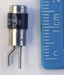
| The first transistors made by Mullard were the OC50 and OC51 point-contact types from 1952. As this image of the OC51 shows, they looked just like a typical Bell Labs “outline #1” case, except that the metal is shinier, and the plastic plug in which the leads are fixed is pale brown. I have three of them and only one has any markings on it, suggesting that the white printing rubs off the black band very easily. These transistors were probably not commercially available: some were probably given to a few research institutes, then Mullard rapidly moved on to junction types.
I am seeking examples of the OC50, and indeed of the OC51 in identifiable form, for example in an original box. I also wish to buy original data sheets for these devices. If you have any of these, please contact me. |
 |
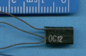 |
The first (grown?) junction types made by Mullard were the OC10, OC11, and OC12 (shown in the image) from 1953. These were all low-power audio-frequency amplifiers, the first two differing in noise level, the OC12 having a higher gain. Unfortunately, it was soon found that the plastic encapsulation was not hermetic, and moisture crept along the leads and ruined the transistors.
I am seeking examples of the OC10, OC11 and OC12. I also wish to buy original data sheets for these devices. If you have any of these, please contact me. |
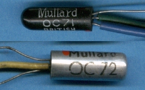
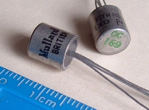
| Mullard then developed a unique glass encapsulation, and in 1954 issued three new alloy-junction audio-frequency transistors, the OC70, OC71 and OC72. The image shows the OC71 glass case, painted black, with below it the OC72, a higher power type, achieved by slipping an aluminium can over the glass tube. The OC70 was a low-noise version of the OC71.
This black glass encapsulation, and the version with the aluminium sleeve, both referred to as SO-2, were used by most of the transistor types in the OC series, although a few types used the TO-7 metal can, and power types used TO-3. A correspondent told me that in the early days of the industry, an apprentice at his company was sacked because he had amused himself by crunching the glass capsules under his boot. At the time each transistor cost a week’s wages! |
 |
| Examples of transistors branded ASM are rare, especially early types. This OC72 is the only such type I have found. | 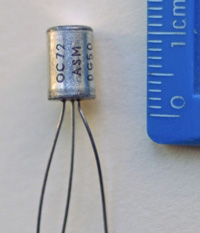 |
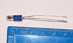 |
Like other manufacturers, Mullard produced a phototransistor, the OCP71 shown on the left. This is a very early type, available commercially from 1956. It is well-known that semiconductor junctions can be light-sensitive, and there is a widely repeated story that the OCP71 was just an ordinary OC71 without the black paint (so-called ‘dope’). Because the OCP71 was more expensive, some people just scraped the paint off an OC71, to create an equivalent to the OCP71. The story then claims that Mullard changed the filler in the capsules from clear to opaque, to prevent this practice.
Thanks to correspondence with an ex-Mullard employee from the Mitcham works, I now know that this story is entirely wrong. At the time, the behaviour of manufactured transistors varied considerably, so devices from one production line were sorted into either OC70, OC71, or OC75 using a Transistor Test Board to measure their performance. These transistors were dipped in a light blue silicon “Bouncing” putty before insertion into the glass capsule which was then filled with Alundum paste: an aluminium oxide and silicon oil mix that was lightproof and also conducted heat away from the transistor junctions. The exterior was painted with a black ‘dope’. Scraping off the black dope therefore reveals a blue tinged whitish interior. However, the OCP71 capsules were filled instead with a clear silicon grease to allow light through. They were tested as phototransistors and those that were rejected were re-tested to see if they met the normal OC7x series parameters. Those that did were sent off to be painted with the black dope and be printed as OC7x devices before being packaged as normal. Therefore, if scraping the paint off an OC71 reveals a transparent interior, this is NOT an early example before Mullard switched the filler, but is in fact a rejected OCP71. Using it as a phototransistor is not a good idea! There exist also OCP70 phototransistors in the same style, an unpainted capsule in a plastic holder. However my experience is that they are invariably unbranded, unlike the OCP71 which is usually marked ‘MULLARD’. I suspect this means that they are generic Philips devices for OEM use. If anyone can confirm this, or has an OCP70 marked Mullard (not an OCP71), please contact me. |
| Philips/Mullard produced the first commercial high-power transistor in Europe, the OC16, in about 1956. The prototype version on the left in the image handles 24 Watts. The commercial version to its right used a different stud packaging in which two leads emerged through a hole in the centre of the fixing screw. This package was only used for the OC16, apart from two exceptions that I know: I have a single OC24 in this package (normally that device uses the TO-3 package), and I possess a strange Mullard type CXT6b, shown below. | 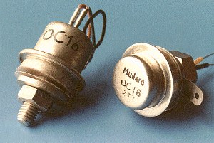 |
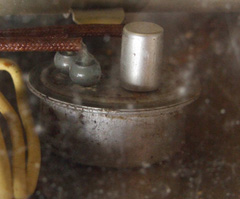 |
However, there was an even earlier Philips prototype power transistor that is exceedingly rare: the OC15. My image of it is rather unclear because it was taken through a perspex sheet. The transistor is part of a demonstration transistor amplifier in a perspex and metal case, probably made for a trade show in the 1950s. It contains two OC71’s, two hefty interstage transformers, and a single OC15. The OC15 should have a paper label but that has fallen off and is trapped in the wiring. I have not yet attempted to open the perspex casing.
This device was probably developed by Valvo in Germany, who originally numbered it 100.O.C. Amperex in the USA numbered it 2N115, although they also used the same number on later OC16 devices. Images of these variants can be seen on Joe Knight’s pages on Jack Ward’s web site. |
| Mullard soon abandoned the proprietary stud encapsulation for high-power transistors, and changed to using the standard TO-3 ‘diamond’ package, as shown in this OC19, another audio-frequency type from about 1962. At this time, Mullard were still supplying their transistors in the same kind of cartons that they used for valves. | 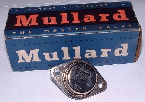 |
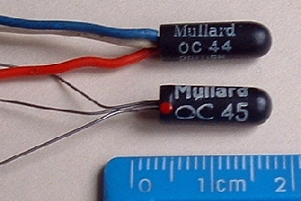 |
Also in 1956, Mullard announced the OC44 and OC45 transistors, the latter seems to be described all over the Web as “the first RF transistor”, although I think this only applies to Europe. In reality these two devices would be more accurately termed IF transistors. There is an ongoing market for the OC45 on eBay because it was used in some early guitar effects units (“fuzz boxes”) and purists insist that only the original will do. There are even people who talk about the “germanium sound”, and do not mean poor signal-to-noise ratio! |
| Like other manufacturers, Mullard believed that hearing aids provided an early application for the transistor, because of its small size, low voltage, and lack of heater circuit compared to valves/tubes. This was ultimately only a minor market, but Mullard created four sub-miniature types, OC57 to OC60, only a few millimetres long, and two miniature types OC65 and OC66, slightly larger. All were audio-frequency amplifiers for use in the output stages of hearing aids. | 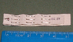 |
 |
The first RF transistors used the alloy-junction fabrication process, which limited their upper-frequency limit. Mullard soon followed the American lead in improving upon this with a technique called alloy-drift, where controlled doping gradients were used. Their first examples were the OC169 (shown) to OC171 in 1959, but later their AF114 to AF118 types from 1961 onwards, using the same TO-7 metal can with shield lead, became standard in the RF stages of British transistor radios.
Unfortunately for vintage radio enthusiasts, many of these TO-7 types showed problems over time, and various very ad-hoc cures were attempted. Investigation by NASA Goddard has now shown that the problem is tin whiskers growing out from the interior walls of the can, ultimately touching the germanium die and shorting it out. |
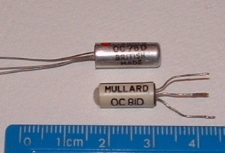
| Mullard made a small number of devices that were intended as driver transistors for audio output stages. These bore the suffix ‘D’, and examples include OC78D, OC81D, and OC82D. For reasons unknown to me, these types often used the SO-2 glass capsule but with a coloured plastic sleeve, rather then being painted black. This is occasionally seen on other types too.
If anyone can explain this, please contact me. |
 |
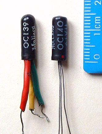 |
Of course, Mullard also produced switching transistors for use in computers and logic circuits. In 1959 they announced a number of these, including the OC41 and OC42 in the SO-2 metal can, and the rather unusual OC139 to OC141 which are germanium NPN types in the SO-2 glass package, usually marked “MADE IN HOLLAND”. All of these devices found widespread use in the UK electronics industry, including computer manufacture. |
| Mullard’s first silicon transistors were the OC201 to OC207, PNP alloy types using the standard SO-2 metal-over-glass construction such as the OC201 shown. These can occasionally be found on eBay, usually advertised as germanium devices! Mullard soon switched to using the BC prefix for silicon, and AC for germanium, eliminating the confusion. Only a few of the BC types are found in the SO-2 metal packaging, such as the BCZ10 shown, most used newer plastic encapsulation. | 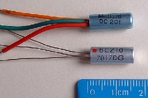 |
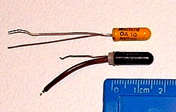 |
Of course, Mullard made diodes as well as transistors, and their OA series found widespread use. They made point-contact, gold-bonded, and junction types, plus Zeners, in both germanium and silicon,. This included subminature axial types, miniature axial types such as the OA81 often used as the AF detector in radio circuits, and switching types like the OA10 in the SO-2 glass package. Most of these diodes were painted black, but sometimes yellow was used. Later types used the AA (germanium) and BA (silicon) prefixes in their part numbers. Zeners had a ‘Z’ in the prefix, e.g., OAZ205. |
| This device is in the same primitive stud package with leads out of the top used for the prototype OC16 in about 1955. Disintegrating greased paper labels are marked “Semiconductor Lab. Development Sample. No guarantee for subsequent delivery.” The label should bear an added written type number, but this is either missing or too faint. | 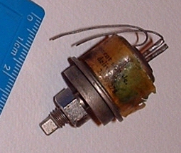 |
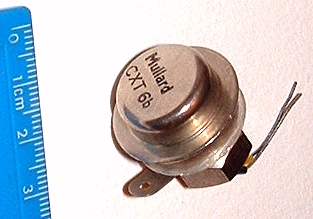 |
This transistor CXT6b is a real puzzle. It is in the stud package used for the commercial OC16, the first Mullard power transistor, which suggests that it dates from about 1956. The only information that I have unearthed is that the 1963 CV Register of Electronic Valves mentions two GPO types, CXT1 and CXT2, with CV equivalents. This suggests that this CXT6b may be a GPO type, probably equivalent to OC16. However, GPO types are usually found in the PO series, itself rare.
If anyone knows about this device or the CXT series, please contact me. |
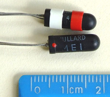
| There are other unusual Mullard types that I possess, but for which I have no data despite possessing many Mullard books and datasheets spanning the whole germanium period. These include type MEI (or possibly ME1) in the SO2 black glass tube but with red and white rubber bands around it, type NC11 in the SO2 metal can, type T1 in the SO2 black glass tube, type T3 in a TO-7 can, type T4 in a TO-1 can, a dual-typed OC16 also marked 2N115, and a type 2N583K in the typical GEC copper can with blue sleeve.
If you know about any of these devices, please contact me. |
 |
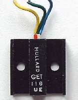 |
This GET116 is an example of a vintage GEC (UK) transistor bearing the Mullard name. This means that it post-dates the creation of ASM, after which GEC branding gradually disappeared. This is borned out by the date code UE which stands for May 1963. |
| Like most UK semiconductor manufacturers, Mullard made CV equivalents of many of their devices. These were military-grade versions of commercial types, given a Common Valve type designation such as those shown. | 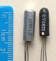 |
©2018 Andrew Wylie all rights reserved
http://www.wylie.org.uk/technology/semics/Mullard/Mullard.htm
Posted in Uncategorized
Comments Off on Mullard Semiconductors

the AC128 transistor
31 January 2019 / by Jacques Charbit
INTRODUCTION: The nanotube
Silicium might be an endangered species. Progress around carbon electronics (nanotube and tripods) and nanotech are going so fast that a well-known Japanese TV brand is issuing next year a flat TV screen using carbon nanotube. Much more than this, in our days of digital technology, it is quite uneasy to find the simplest Silicium transistors essential for fuzz box craft.
In this context, it may seem ridiculous to focus on the old germanium electronic science, which main actors are just fond memories of the past.
Nevertheless, and I am not the only one to think this way, nothing sounds half as good as a well-tuned germanium distortion device for electric guitar.
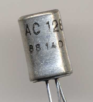
This is why today, I would like to introduce you to my old buddy, the AC128 germanium transistor ,
exclusively used in my handmade Mercer Box and KATAPULT pedals .
Besides being in the famous original Fuzz Face, the AC128 was used in numerous domestic electronic appliance, and certainly one of the most common European transistor. This explains why it is still possible to find nice new-old-stock of these jewels.
They usually come in 3 different types :
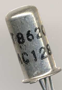
The real thing
This is both the oldest and arguably the best sounding AC128. It is very similar if identical to the infamous NKT275 which equipped the original Jimi Hendrix grey fuzz face .
But this wonderful piece of crap has a major drawback : completely random technical data in a VERY wide range. This means that any given theorical design has something like 30% odds to function right away. This fact has 2 consequences:
1- Each distortion device using this same transistor must be modified afterwards to match the theoretical technical data of the set of 2 or more transistors.
2- This a posteriori adaptation must be made while monitoring the tone of the resulting distortion in order not to drift away from the prototype.
Nowadays cheap transistor tester are avaible widelyso transistor selection is a tad easier.
It is therefore easy to understand that this kind of transistor is not industry compatible. Only handmade and hand-tuned devices can benefit from this nasty gremlin. Beauty has its price.
The hottie
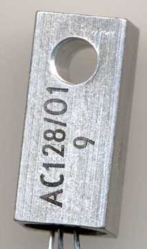
This strange device is exactly the same transistor BUT with a factory mounted radiator, useful in other applications where it receives its 32v possible supply. The AC128 can be as hot as a soldering iron in certain cases with no damage. Compare this to a ts9 chip.
You will find these square beatuies often in a matched pair with a AC127. Those pairs were used in the not-so-distant past for making small amps that will go in radio, record players etc … remember the Queen deacy amp was powered by ac128 as power transistors.
I feel the radiator somehow tightens the fuzz tone, while not in a big way, making it a valuable successor.
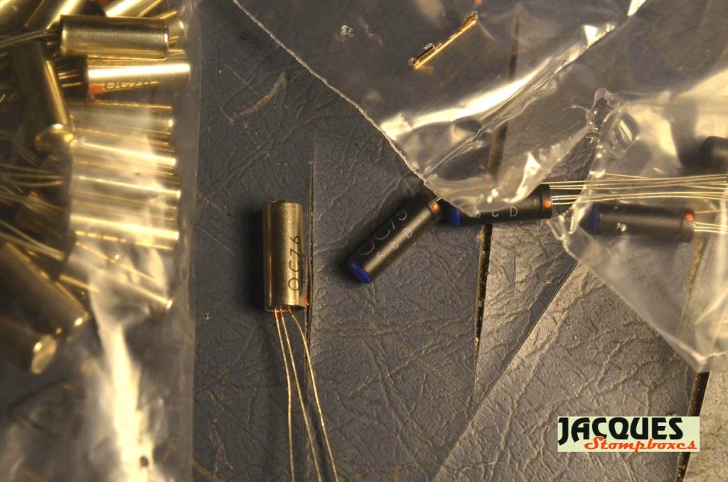
The modern
Well, they were the last poduction AC128 and can be found easier in new old stock. Their data is even more erratic , with hfe gain going from floor to roof in the same batch. I don’t recommend them for beginners.
Unfortunately,while really good in booster / one-transistor pedals, this young component gives a higher even/odd harmonics ratio in fuzz pedals than its pain-in-the-ass ancestor. So the resulting distortion is , exaggerating, closer to a metal zone than a fuzz face.
They are precious anyway, as they fit in the original fuzz face design without any change and give a very acceptable approximation, even for a purist. They really are pure germanium after all!
The little sister
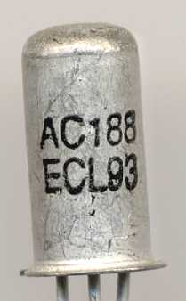
The AC188 pictured here, is a scaled down version of the modern AC128, made for lower voltage applications. And what are our 9v fuzz box ? In fact , this little sister does miracles with electric guitars.
Pushed to their limits, they deliver a full frequency grawl that is hard to beat. A very interesting transistor indeed, the AC188 is too rare to give its full dimension but remains one of my fave if you know how to use it.
the OC family
OC prefixed transistors were made by Mullard and Valvo , and are famous among pedals aficionados because they were present in famous classics such as Marshall supafuzz and eraly vox tonebenders. They usually are good quality and good sounding. The oc75 seems to have been manufacured or selected for good and constant Hfe , making it a perfect choice , while the oc76 must be sorted but yet is also a great choice for fuzz pedals. I can imagine OC75 were selected OC76 , just like Philips were offering different selection for their great dac chip tda1541 .
The Frenchies
The first transistor to be produced in France was invented by Doctors Welker and Mataré of the Société des Freins et Signaux Westinghouse (F & S Westinghouse) in mid 1948 and announced to the World in May, 1949
In the world of fuzz, some french transistors made their way to history such as the SFT352 present in the famous Elka Dizzy Tone which was at my time a modest copy of the tonebender.
But in 1962 , the two companies present in the early days,
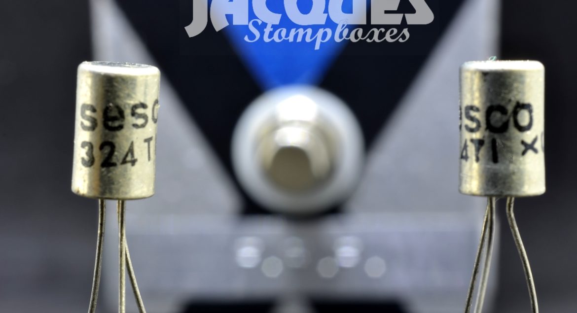
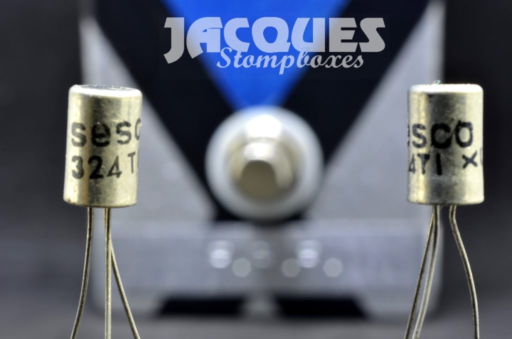
Thomson-Brandt and CSF merged into two new firms , COSEM in the French Alpes and SESCO in Aix-en-Provence , a few miles away from my hometown, Marseille.
So it’s no surprised I found here nice supply of germanium transistors from SESCO, including my fave, the 324TI which has perfect HFe and noise level for fuzz pedals.
These means I can do a nearly 100% made in Marseille pedal, which I call the F.F.F. ( French Fuzz Face ) . Please send me a note if you’re interested.
EPILOGUE : When supply will dry…
In a very close future, all stocks, including mine, of original germanium AC128 or any usable germanium transistor will dry.
Forever.
After this extinction, that only a few aficionados will notice, there will be no other possiblities to obtain THE original fuzz tone than a used Germanium fuzz box or a digital model.
Make your choice.
From my point of view, I feel my ’65 strat deserves more than a plastic computer. And in my experience, no digital guitar tone can sound good live or even recorded.
” How well you know me
You’ve seen me cry
I’m just a shadow
In a rock’n’roll sky “
Deep Purple 1973 “Super Trooper”
Posted in Uncategorized
Comments Off on the AC128 transistor
“5F” – The FAQ For Fuzz Face Fanatics
By Steve Daniels, Small Bear Electronics LLC
© 2018 By Small Bear Electronics LLC
This article answers some common questions about the transistors used in cloning and modifying the Fuzz Face and similar pedals. It is meant for beginners who are confused about what devices to use and where to get them, and as a reference for more experienced DIYers. I wrote it in 2000 when I first began offering matched germanium transistors. I have updated it several times since to reflect things I’ve learned and changes in the old-stock transistor market.
-
- What transistor types are best suited for the FF?They should be germanium if you want to get the classic 60’s/70’s “soft” distortion. Silicon has been used, and many people like the harsher clipping, but it is a different sound. Among germanium transistors, many type numbers (see the list below) are possible candidates for FF circuits and clones. However, careful sorting and testing are needed, because wide variations in gain and leakage among devices with the same part number are the norm.
-
- Why the wide variation?Manufacturing techniques in the ’50s and ’60s when germanium was the material of choice were not nearly as precise as they ultimately became.
- What should the gains be? The usual recommended range for the “classic” Fuzz Face is 70-85 for Q1 and 120-140 for Q2. However, if you like a sound that’s more “squishy” and “compressed,” I have found that a high gain device for Q2 (150-190) gives a good result with a Q1 in the range of 90-120.
- Do the devices have to be the same type number? Do they have to be any particular type number to guarantee great tone?No and No. I have used pairs made up of completely different types; they work very nicely as long as neither device is too leaky and the gains are in buckets that permit correct biasing. Given the wide variation in characteristics noted earlier, the emphasis on getting particular type numbers is misplaced, IMO.
- I have a NNNN pedal. Will I get better tone if I replace the existing transistors with XXXX?If the pedal already sounds good, it is hard to say. In the first place, your idea of “better” may not be mine, or anyone else’s; personal tastes vary enormously. Beyond that, getting good results when modding a pedal requires knowing the characteristics of the pedal, the specs of the devices you intend to use, and often something about changing component values to make the marriage work.
On the other hand, I often get this question with respect to replacing cruddy, poor-quality or poorly-matched transistors in some “Name” commercial pedals. In that case, the answer is: Yes, if you know what you are doing. Be aware that the replacement is not nearly always a “drop-in”; it may involve trimming bias resistor values and/or adding transistor sockets to the board. If you are a beginner, you should do a lot of homework before proceeding or get knowledgeable assistance, and maybe both.
- How do I get a matched pair?You can buy a bunch of devices (sometimes available from repair shops, wholesalers, surplus outlets or on-line auctions) and experiment, or pay a few bucks for a pair of devices that someone has matched for you.
- What should they cost?If you get lucky (or you’re very persistent), unmatched devices can still be had for surplus prices. However, just as you no longer find old Martin guitars going begging in flea markets, word of the value of certain electronic devices has spread among those who have them. For the moment, decent-quality old-stock parts are still available, if not as dirt-cheap as they once were.
In general, the price per transistor will rise commensurate with scarcity of the particular type. Beyond that, a reputable seller should tell you whether the devices are matched and audited, completely unsorted, or “rough-sorted.” Caveat Emptor! Especially if you are buying a wholesale lot, know your seller! Fakes of famous type numbers have become rife, and many lots will turn out to have been “cherry-picked.” It is depressingly easy to get burned even buying something you think ought to be a real score–like that lot of 2N404s that you thought would make great Tonebenders, but they all turned out to have gains in the 40s.
- What devices do you use to create your pairs?My present U.S.-made raw stock consists of branded and unbranded, old-stock devices, mostly in TO-5 cans. The branded PNP parts are mostly 2N404, 2N404A or 2N321, and the unbranded are roughly similar to the old 2N1307. At one point I scored a lot of Texas Instruments 2G30x, and more recently a bunch of Amperex 2N281. My Chinese devices are 3AX31C. I sort and test to the following spec: With a 9-volt supply, collector-emitter leakage under 300 microamps at room temperature with the Base open. With 9 microamps base current, minimum “real” gains of 80 for Q1 and 110 for Q2. I also audit every pair to eliminate hissy devices, and I provide a record of the bias resistances I used when testing. See the Stock List
- Which of the pairs you offer is best for upgrading a Fuzz Face?Any of the matched pairs will work, and will sound good to most ears if properly biased. “Best” is invariably a matter of personal taste. See my guarantee/warranty below.
- Which of the pairs you offer is best for building a Fuzz Face?Any of the matched pairs will work, and will sound good to most ears if properly biased. “Best” is invariably a matter of personal taste. IMO, as long as the devices aren’t excessively leaky and hit reasonable gain buckets, the make of the transistors is much less important to the tone than the values of the input and output capacitors. If you are seeking the holy grail, learn to breadboard (See the articles in How-Tos) so that you can see which ones grease your crank. Also see my guarantee/warranty below.
- Why would two devices with roughly the same gain and leakage sound different?To paraphrase R. G. Keen: “There is no such thing as “mojo” or “magic” in the physical universe.” However, since knowledgeable players have noted this difference, we can reasonably say that there are internal electrical properties of some transistors (internal capacitance has been suggested as one) that do affect the perceived tone, and don’t appear in the published specs.
- Do your more expensive pairs sound better than the less expensive ones?In my opinion, no. The difference in price is driven entirely by the relative scarcity, differing costs and yield of useable parts of the raw stock that I start with. That said, pairs made from devices that came from different manufacturing environments Will, often, sound different from each other. Knowing that these devices are as individual as snowflakes, and that customer tastes vary enormously, I offer the guarantee in the next FAQ.
- What guarantee do you offer?/Can you provide specific gains?I guarantee that your pair will sound “like a Fuzz Face” if used with the resistor values I recommend. The devices can be returned for credit or refund as long as they are not soldered and have full leads. Try them out on a solderless breadboard and/or use transistor sockets to make sure you’re happy.
In any lot of raw stock, there are always only so many parts in the 70-85 and 130-140 buckets that everyone wants. A 20% yield is is typical. So, in order to keep these devices affordable for DIY, I don’t guarantee to provide specific brands and my allowable range of gains is necessarily wide. Q1 may vary from 80 to 110, and Q2 may go as high as 199. We fill orders by picking from a “grab bag,” so what you get is strictly luck of the draw.
If you have to have a pair in the “classic” range, consider buying a small bulk lot (SKU 0115 for the spec, SKU 0115A for the smaller bag) and sorting your own. You can also troll E-Bay, with the caveats that I mentioned earlier. I guess the bottom line is that you Can find the holy grail, but it will, inevitably, cost some money and probably time, as well.
- A bunch of people have asked me to build pedals for them. Will you discount for quantity/provide quantities of matched pairs?This has come up a lot in recent years with the spread of small-volume pedal-making. I do not discount matched pairs, because there is no economy of scale in the testing. Whether I create one pair or a dozen, it takes the same amount of hand work per pair.
We cannot provide quantities of audited devices to commercial builders, and we purposely limit the number of pieces that we will sell to any one customer. For the boutique trade, I do offer rough-sorted, bulk lots of unbranded devices. Please see the Stock List for available types and specs.
Bulk lots also exist with many wholesalers, both here and overseas, but their minimum orders are usually out-of-reach for hobbyists. Those shops are sometimes alternatives for commercial builders who have the need, the ability to fund a large order, and a very high tolerance for risk. You will get lots of leads to possible sources if you do a Google search on “Germanium Transistors.” But be aware that the market is totally unregulated, full of trash and very difficult to navigate.
- If I want to hunt for my own devices, what type numbers do I look for?This list of “candidates” may help. It is a compilation of things I have seen on other bulletin boards (Aron Nelson/Jack Orman/R. G. Keen), and my own experience with Japanese and American parts.
American JEDEC numbers
PNP: 2N321, 2N404, 2N404A, 2N508, 2N527, 2N1305, 2N1307
NPN: 2N388, 2N1306, 2N1308, 2N1309, 2N1373
American “Replacement” Types
NTE (or ECG) 101, 102, 158
Japanese
PNP: 2SA or 2SB 22, 54, 75, 77, 172, 175, 178, 187, 201, 303, 324, 370, 405, 439, 516
Of these, the types that have given me the highest yield of “good” devices are the 2SB175 and 178.
European
PNP: OC44, OC71, OC75, OC77, OC81, AC122, AC128, AC151, NKT275
NPN: AC127, OC140
- Why are NPN types usually scarcer and more expensive?According to R. G. Keen, the physical characteristics of germanium made it much easier at the time to manufacture PNP devices rather than NPN. The demand for non-leaky, temperature-stable NPN devices of consistent gains was one of the factors that drove germanium out of the picture in favor of silicon. The result is that, today, there are large, fairly dependable supplies of old-stock PNP germanium on which I can draw. I have also secured some stock of U.S. and European NPN types.
- Do you offer any of the Western European types (NKT275, AC12x, OCxx, etc.)?I have a few OCxx types, and we offer matched pairs of some. If you do go looking for European numbers, buyer beware! The old-stock devices have become very expensive, and fakes are common. AFAIK, devices marked NKT275 are all re-labeled. They may or may not be decent quality–that depends on what raw stock the seller started with–but they are almost surely not the same devices that Newmarket sold back in the day. The modern re-makes of some AC12x have a poor reputation for quality.
- What about Russian parts?They are remarkably good, and good value for money…consistent in gain and not leaky. The high quality probably relates to the fact that many of these devices were made for the military. Back in the (very bad) old Soviet days, the army got some of the few good things that local factories were making. If you can tolerate some unusual pinouts, try a pair.
- Did you say CHINESE??Absolutely. Thousands of these were sitting unused for decades in warehouses in Shanghai, and I have a large lot of 3AX31C (PNP). They sound a bit more trebly to me than my U.S.-made stock, but I don’t hear any “mojo” that would justify a huge price difference compared to other types. I suggest that you take any on-line hype with a large dose of soy sauce. However, they are very good quality, and suitable for any of your favorite classic builds.
- Will any/all of your pairs work in the various clones of the germanium Fuzz Face, e.g., the Vox Tone Bender, Fuller Mods, Hendrix Mods?We audit all pairs in the classic Fuzz Face circuit, and we guarantee proper operation in that circuit and with the bias resistor values that we specify. That said, any of our matched pairs can usually be made to work in any of the clones. However, be aware that the bias resistor values in the published schems usually presume that the transistors hit the “ideal” gain range. You can still get good results with pairs that don’t fall in that range, but some tweaking of the bias resistors will be needed. If you are building something other than a classic Fuzz Face, testing on a solderless breadboard is highly recommended.
- What about using them in the germanium-silicon “hybrid” designs?Some of these, like Joe Gagan’s Easy Face, have become very popular. They offer a very wide range of tonal possibilities, and they tend to be less sensitive to temperature variations than the all-germanium FF. Regardless of type number, any device that meets the designer’s recommendation for gain and isn’t too leaky will work. I offer U.S.-made devices that have the right gains for the Easy Face and for Aron Nelson’s Hornet. Again, as I am able to train people to do the auditing, I hope to offer a greater variety of specific device types.
- What about the three-transistor set for the Sola Tone Bender Professional Mark II?The second and third stages are exactly the same as in the Fuzz Face, and the first stage needs one that measures from 75-100. Check the postings on diystompboxes.com for suggestions on how to tweak the bias. I offer a tested three-transistor set. See the Stock List.
- Will “replacement” devices work?If you get lucky. These devices (NTE, ECG, SK, etc.) are actually factory rejects from major transistor makers that have been sorted into rough (VERY rough) gain groups and re-labeled. In general, they are not a good buy; way too expensive, too variable in their characteristics and often excessively leaky.
- How do I measure Gain?Based on an explanation of the basics from R. G. Keen, I worked out a bare-bones method for getting an estimate of the static DC gain of a transistor, good enough for sorting devices for the FF and clones. You’ll need the following:
- A DVM
- a 1 meg resistor
- a 9-volt battery or power supply
- a few test leads with alligator clips
- The temperature sensitivity of older germanium transistors has to be seen to be believed; when setting up these tests, only pick up the devices using tweezers or wearing gloves. The polarities of the battery and meters are shown for PNP devices; they are reversed for NPN.
First, measure the leakage current:
It may take a few minutes for this reading to become stable. (I swear that some of the ones I have tested are reacting to variations in room temp and/or my body heat!) Record the figure on the meter. This is the leakage current.
Keen has noted that too much leakage makes suspect the long-term reliability of a device. How much is too much? My own spec has always been to reject any device that leaks more than 300 microamps at room temp.
Now apply forward base bias through the resistor:
Again, wait for a stable reading. Record the figure for collector current.
Do the following arithmetic to get Hfe:
(Collector Current – Leakage Current) __________________________________________________________ Base Current (all values in microamps) The base current will be 9.0 (microamps) if the resistor is exactly 1 meg and the power source is really 9 volts. The normal 5% tolerance of a carbon film type will get you close enough, though R. G. Keen has pointed out that you can use the resistance scale of your DVM to select one that is closer. - Why should I use this method rather than using a DVM with an Hfe scale?Unless you know exactly how the DVM measures and calculates Hfe, you should presume that it doesn’t take leakage current into account. This would give an incorrectly high reading of Hfe on a device that maybe you shouldn’t be using at all.
The method described here is crude, but the only way to do better would be to spend money for a scope/curve tracer. The results you’ll get from the bare-bones method are close enough to select pairs that will work well in the Fuzz Face circuit with no trimming. I have focused entirely on practicalities, so if you want an explanation of how the Fuzz Face works and why gain matters, go to the scriptures:
Posted in Uncategorized
Comments Off on “5F” – The FAQ For Fuzz Face Fanatics
Ultra Simple 9v VCF

This VCF (Voltage Controlled Filter) is made from a tl071 op amp chip, 6 resistors, 3 capacitors, 2 pots and a diode. The schematic is very simple, and takes about an hour to build (less if you’re good at this type of stuff). In this video I am generating a square-like wave using my 4093 based VCO (the round black module on the right), which is fed into the VCF (the middle one with the white and red striped-base). Midway through the video I turn on my 4017 Sequencer, whose output goes into the CV input of the VCF. This turns the solid note into a sort of harmonic/overtone melody, which can further be manipulated by adjusting the filter/sequencer. The resonance pot at full resistance turns the wave back into it’s original form. At little or no resistance you can see the waveform is more strongly influenced by the cutoff pot. The cutoff pot adds (or takes away) harmonics/overtones depending on how you manipulate it. I highly recommend this circuit. It is very easy to build, has very common component values, and makes every instrument sound crazy. I can plug my guitar into it and get a good Frank Zappa “Black Napkins” effect when my sequencer controls it.
Posted in Uncategorized
Comments Off on Ultra Simple 9v VCF