
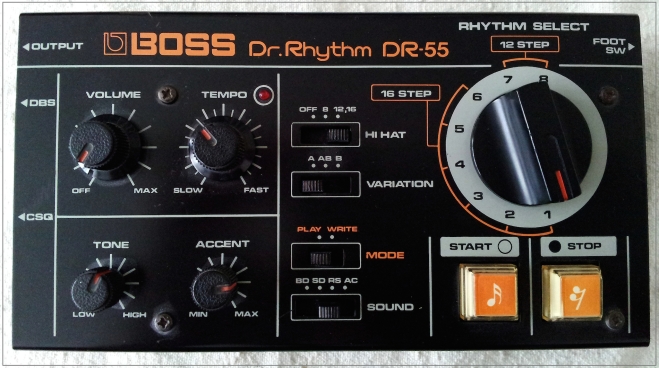
DR55 does have an authentic sense of early 80s legendary nostalgia…
being BOSS’ first DR-machine and also quite a successful early programmable drum machine.
It has been used by New Order, The Cure, Chris Carter, Sisters of Mercy, Chris & Cosey, Soft Cell and Thomas Dolby.Boss DR-55: external trigger input mod
By default, the Boss DR-55 does not receive any kind of incoming clock. The ‘FS’ footswitch input takes a latching footswitch that starts and stops the existing clock, but that’s it. Although you can clock other equipment from the DR-55, it would be nice to be able to use an external clock to sync the Boss to, which would allow the Boss to trigger yet more devices with its CSQ and DBS outputs (active on Accented steps only and every step, respectively).
My mod as detailed here does exactly that. By replacing the existing FS jack socket, adding a small circuit, and replacing a jumper, we can safely trigger the DR-55 from an external trigger.
A quick internet search will turn up an existing clock input mod which is simpler to do and requires no extra parts; however, it puts the RAM at risk of damage from high triggers, and it does not sync the Boss’ own DBS output. It also requires ‘arming’ by hitting start before external triggering.
My own mod, though more complex, overcomes all these issues: the trigger input is protected, both the Boss’ trigger outputs maintain their correct functions, and triggering occurs without ‘arming’. The only two functional disadvantages of my mod are that you must set the Boss’ tempo to Fast, and to reset the pattern when stopped mid-way you need to remove the trigger plug. I’m going to blog another small mod which will overcome the latter inconvenience [EDIT: No I’m not! I sold both my 55s, thereby halting this particular project].
The Clock Modification in detail
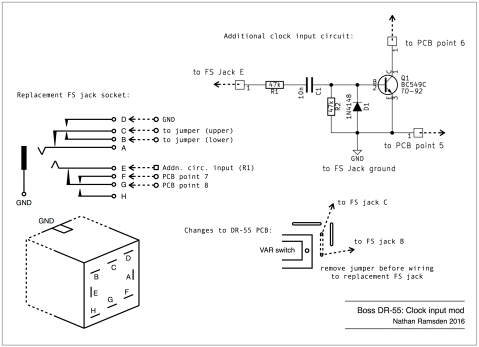
Below is a diagram which shows everything you need to know about building this mod. Below that is a parts list. Key to this is the replacement FS jack socket; it needs to be TRS (ie. a stereo jack), with single pole changeover switches on the tip and ring contacts. I used a Lumberg KLBPSS3 (datasheet here, Farnell UK stock page here).
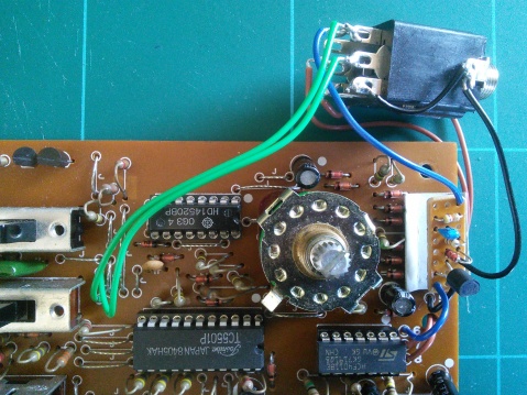
The additional circuit can be made very small indeed (3 rows * 8 holes on stripboard), and there is plenty of room for it inside the DR-55, particularly towards the right-hand end. The photos below illustrate my own placement.
There is one jumper to be removed, the one immediately to the right of the Variation switch. The replacement connections for the upper and lower point of this removed jumper are shown in the diagram, and you can see in the photos how I wired this up.
In brief: remove that jumper, solder the two points to two jack pins; build the extra circuit, and solder that to the jack and to the main PCB; replicate two of the pre-existing connections from the jack to the PCB. That’s it. I also stuck a small folded piece of card to the PCB to stop the extra circuit from shorting against components.
Boss DR-55 clock input mod
Boss DR-55 clock input mod revised
Parts list:
1 * TRS 2-pole changeover jack socket – eg. Lumberg KLBPSS3
2 * 47k resistors – I used 1/8W for their smallness
1 * 10nF capacitor – I used a ceramic, again for smallness, but polyester film etc. would be usual
1 * 1N4148 signal diode or equivalent
1 * BC549C transistor or similar standard NPN
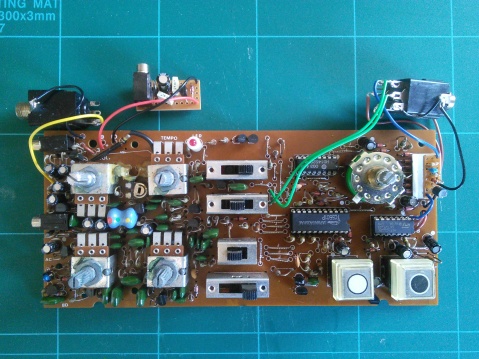
Here’s the modified DR-55 (also incorporating my DC supply mod):
clock modded DR-55 overview
clock modded DR-55 overview
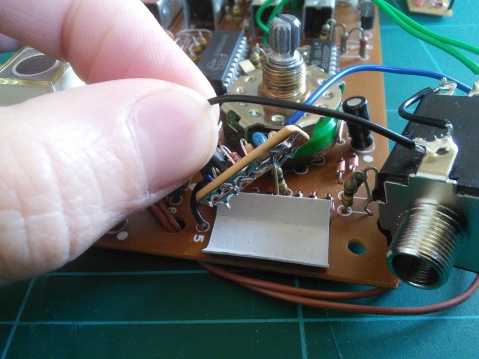
And here’s a close-up of the clock mod:
clock modded DR-55 close up
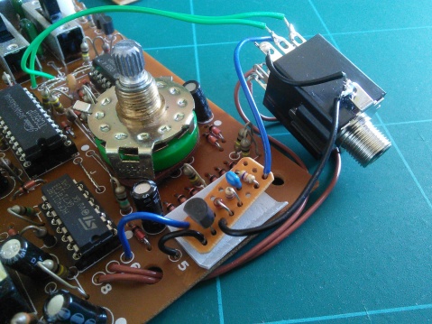
clock modded DR-55 close up
How to use your new trigger input
The new trigger input will accept any positive pulse over a couple of volts. It’s edge triggered, so the pulse can be any length over a couple of milliseconds. The operating principle is to use the DR-55’s existing clock, but to gate it on for a very short duration; normally when the clock is gated off again, the pattern resets, but the new jack socket enables us to disable that by breaking the reset connection when a jack is inserted.
As I mentioned earlier, the Tempo must be set to Fast (ie. all the way clockwise) for correct function. This is because the DR-55’s clock, once triggered, finishes its pulse cycle. If this is longer than the incoming trigger cycle, it will ignore the new trigger; if we set the speed dial to its fastest, we can clock the DR-55 at any rate up to its natural maximum.
The pattern will cycle round as usual, but if you stop mid-pattern, new triggers will continue where they left off. To reset the pattern at this stage, you need to unplug the trigger jack and hit Stop. This is not ideal, I know, and I will be making an amendment to correct this later [EDIT: project halted, see above. I have no current plans to do any further work on the DR-55].
For now though, this mod works fine, as shown in the (slightly rubbish) video below:
Boss DR-55: a 9V DC input modification
One of the drawbacks of the DR-55 as it comes unmodded is the power supply. In its original form, the DR-55 takes only batteries, and though this might be good for reducing cable clutter and having to find yet another wall-wart, it does mean you need to keep a regular stock of fresh AAs, and can guarantee that just when you want to use it, your DR-55’s batteries are too drained for the unit to function correctly.
Luckily, it is a relatively simple process to modify the DR-55 so that it takes a commonly-found 9V DC supply instead. I provide instructions for this below. It’s not the only way to do the job, but this is how I did it, and it works just fine. Modding the DR-55 in this way means it no longer accepts batteries, which means two things: 1) you will need access to a 9V adapter, and 2) pattern data will not be retained on power-off. Given that filling the memory of this humble machine can be done in less than five minutes, and I never use this outside my own home studio, I never found memory retention to be an issue. It would be possible to design a DC input that also catered for memory backup via battery, but I’m not going there.
There are two basic stages to this modification:
Making a 9V DC input: the basic voltage supply circuit
Installing the Mod: adapt some wire links on the output jack and PCB
Because the DR-55’s RAM can be killed by voltages higher than around 7V, we take a 9V input and regulate it down to between 5V and 6V. I chose to use a 5V regulator propped up with a diode to give around 5.6V, but you could also use a 6V regulator and omit D2. The input jack I used is a 3.5mm mono minijack of the kind often used for audio and CV interconnects, mainly because I had lots of them and the holes are easier to drill than the larger ones needed for a plastic-bodied insulated barrel connector. Use whatever type you prefer, but note the polarity of your incoming DC, and don’t connect the +ve to the case… with a tip-positive 3.5mm jack, the sleeve of the input jack is connected to the shell of the socket, so it makes sense for that to be the ground. Some barrel connectors do likewise.
Here’s the schematic:

Boss DR-55 DC input mod schematic

Here’s the final circuit built onto stripboard. It will be panel-mounted using the socket:
DR-55 DC input build
DR-55 DC input build
Installing the Mod
Now we have a simple DC input, we could just solder the +ve and Gnd outputs to the corresponding solder points on the main board – that is, where the battery clip attaches. Black is ground, red is positive. This works, but you still need to insert an audio cable to turn the DR-55 on. I chose to remove that ‘feature’, as there are no longer any batteries to protect from accidental drain. It’s a simple mod that just means a couple of wiring changes.
The diagram below shows the required re-wiring. The audio output socket is wired by default to both ground and audio signal, as well as having two pins wired to act as a switch when a jack is insterted. We want to retain the audio and ground connections, but not the switch. We remove those wires and instead bridge the corresponding points on the PCB.

Here’s a photograph of the full mod (note the wiring):

DR-55 DC input wired and complete

I damaged a track while desoldering the battery wires, which is why the red wire goes to the un-numbered hole next to point 9. They’re directly connected, happily.
Below are some photos of the hole I drilled for mounting the new DC input, and the final appearance when mounted and labelled with cheap Dymo (should have gone with black… oh well):
DR-55 DC input enclosure drilling

So there you have it. My humble DR-55 now works from a regular 9V DC wall-wart supply, and switches on whether or not its audio is connected. The hardest part is putting the DR-55 back together again…
or you can just use old hacked (w/ 9v battery connector)phone charger from cheap Samsung 5v pay as you go track phone…
operating power range from the service manual for BOSS DR55 is 4.5v to 6v
Works for me!
next step external trigger inputs & outputs for each drum sound
http://manuals.fdiskc.com/flat/Boss%20D … Manual.pdf
https://synthnerd.wordpress.com/2016/05 … input-mod/
it’s obviously not a TR808 or TR909 yet picked it up ages ago for $20 in the original box ![]()
replaced bad cd4011UB chip…
for getting the clock working on this old machine
was going to buy the CR55 DIY eurorack then remembered had this old gem
Well, this weekend I met up with a friend of mine who also has a BOSS DR-55 Dr.
Rhythm (groovy, groovy, groovy).
So I say to him, ‘Hey, have you modified the bass drum decay?’, and he hadn’t so
we flipped the top off and had a look inside…
On my DR-55, in the bottom left (near the tone pot) there was a little trim-pot
which varied the kick decay, but on my friends there was only a resistor. Later
study of the service manual shows that only early serial number DR-55s have the
trim pot, so if you’ve a later rev. DR-55 here’s the extremely simple way to
modify the bass drum decay..
The resistor is in the lower left of the circuit board (looking from above),
just below the tone control. ‘BD’ is stencilled on the PCB next to it, and the
resistor is over a little stencilled trim-pot picture. The following ASCII
diagram should help you locate the right resistor.
/-\
l l Tone Pot.
\-/
o
o
o ^
^==/ <<– Resistor to be replaced.
Simply snip out the resistor, and replace with a horizontal trim-pot of several
K ohm. The trim pot goes between the three holes in the silly ASCII diagram
above, with the wiper terminal attached the middle/rightmost hole. I used a 2.2K
that I had floating around (what? your parts don’t levitate like mine? freaky),
and that gave a reasonable control range…